9.1 THE PRINCIPAL INTERCONNECTING COMPONENTS AND MOUNTS
In section 1.4, we briefly introduced the principal interconnecting components and structures. Figure 9-1 shows these for a typical turbopump-fed engine system. A discussion of the most frequently used components follows. Design detail is presented in subsequent subchapters.
Propellant Supply Ducts
Among the principal interconnections between engine and vehicle are the propellant supply ducts. Since every psi of propellant tank pressure above the minimum required for proper engine performance results in additional weight of the tank walls and of the gas pressurants, it is desirable to keep the pressure losses between tank outlets and engine inlets to an absolute minimum.
The task of designing these ducts, or at least the flexible portion thereof immediately upstream of the engine, frequently falls to the engine designer. The designer must find an optimum balance between low pressure drop, by making the duct diameter as large as possible, and flexibility and structural integrity, which in general becomes more difficult with increasing diameters. The designer must further consider the fact that the ducts, because of their location off the engine gimbal center, are subjected to torsional loads, in addition to bending. Furthermore, the ducts are subjected to internal pressure, frequently in a stringent cryogenic and vibration environment. Because of the many forces acting upon the ducts, restrainers against buckling are frequently required. These may be located inside the ducts, thus adding to undesired pressure drop; or they may be applied externally, which increases the duct envelope and may cause interference with other vehicle systems. Figure 9-2 shows a typical nexible propellant supply duct which has restraining linkages for stabilizing the bellows. At the vehicle end, these ducts will connect to longer or shorter vehicle ducts. the length of which depends on whether the forward or the rear tank is being connected. It is important that the engine designer not only inform the vehicle builder of connecting flange dimensions and types of gasket being used but also of the forces transmitted by the engine duct to the vehicle during gimbaling as well. In most pump-feed systems, the working pressure of propellant supply ducts usually does not exceed 50 psig. In upper stages, during lower stage boost, however, pressures may temporarily be substantially higher as a result of a combination of high accelerations and full tanks ( 100 psig and over).
Figure 9-3 shows the propellant ducting and mounting for a cluster of four storable propellant pressure-feed engines. The thrust mounts are of a box-type, beam construction. The propellant ducts, which consist of restrained bellows and rigid sections including flowmeters, connect the thrust chambers to the main propellant valves. The main valves, in turn, connect directly to the propellant tank ducts. Care has been taken in the design to keep the flow path and ducting volume constant between main valves and individual chambers. This arrangement also assures uniform pressure drops to all thrust chambers. Furthermore, all interconnecting components on the fuel side as well as on the oxidizer side are designed to be interchangeable. The valves used in this design include burst diaphragms. Thus, exposure to the propellants of all ducting downstream of the valves will occur only during engine firing. In most pressure-feed systems, the working pressure of the propellant ducts is less than 500 psia .
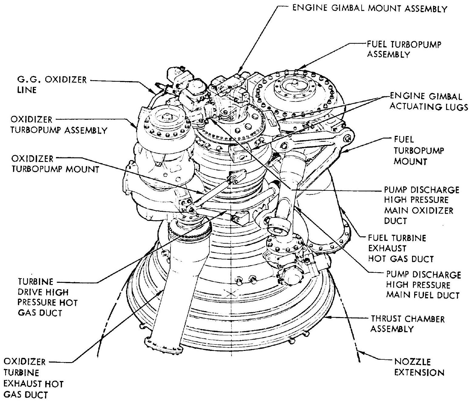 Figure 9-1.-Various interconnecting components and mounts in a typical pump feed engine system.
Pump-Discharge, High-Pressure Propellant Ducts
In turbopump-fed engines the pump-discharge high-pressure propellant ducts are designed to connect the oxidizer and fuel pump discharges to the main oxidizer and main fuel valves attached to the thrust chamber. The ducts contain bellows sections which permit the degree of movement required between thrust chamber and turbopump to accommodate tolerance buildups. misalinements, and motion due to temperature change and acceleration loads. However, in some engine designs rigid, in place welded ducts have been successfully applied. The working levels have been proposed. Therefore, the sepa- rating pressure loads acting on the two components connected by a flexible member must be absorbed by restraining links attached to the bellows, or by other compensating means.
Figure 9-4 presents a typical pump-discharge, high-pressure propellant duct with external restraining links. It is used for the main oxidizer ( ) duct of the engine system shown in figure 9-1. Another typical pump-discharge, highpressure propellant duct, used as the main fuel duct for the same engine system, is shown in figure 9-5. This duct has a unique end-load compensator which incorporates two bellows tied together by a restraining rod to limit bellows movements. One bellows opposes the other in
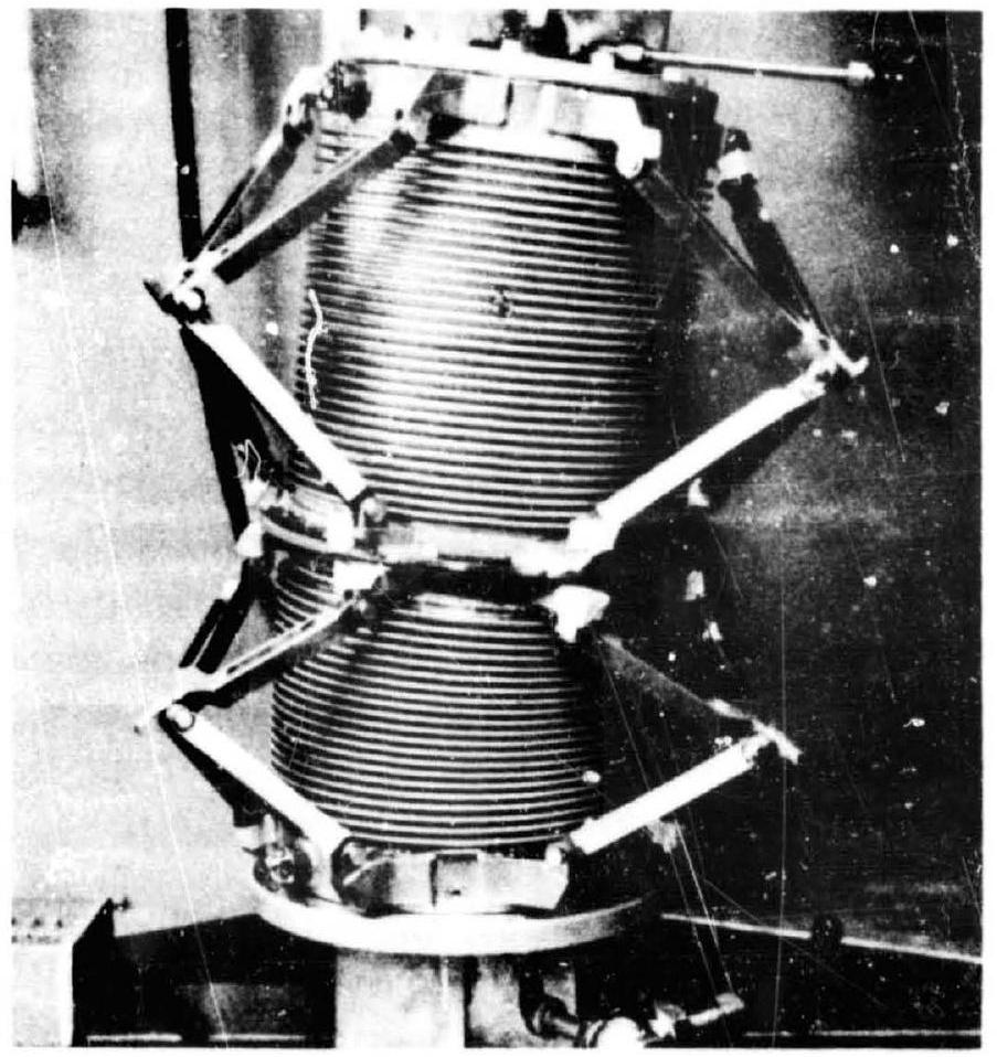 Figure 9-2.-Typical flexible propellant supply duct for a large turbopump-feed engine system. (Note: Duct is mounted in test fixture with fluid pressure connections.)
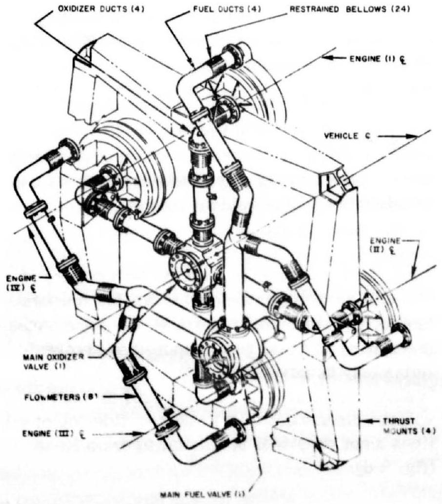 Figure 9-3.-Fiopehuat ducting and mounting arrangements for a cluster of four storablepropellant pressure-feed engines.
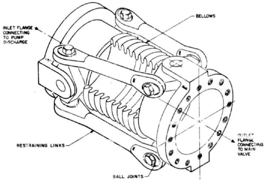 Figure 9-4.-Typical pump-discharge, highpressure propellant duct with restraining ling.
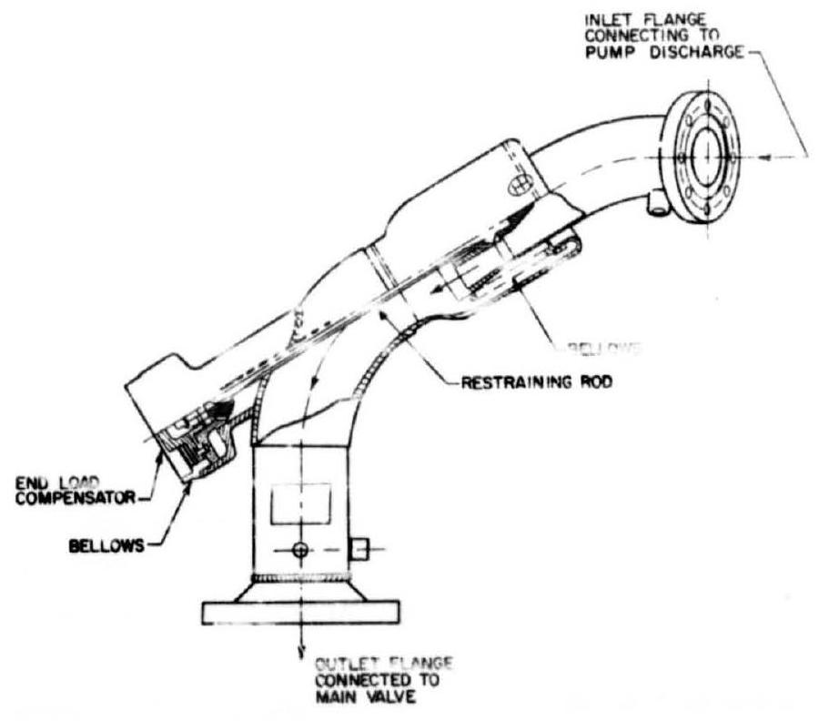 Figure 3-5.-Typical pumpdischarge, higipressure propellant duct with end-load compensaior.
balancing the duct, thus reuncing duct-separating loads by 90 percent.
The high-pressure propeilant lines between pump discharge and gas generator usually can be made of wire-braided-type flexioie hoses or tubing, because of their relatively smail size (often less than 1 inch).
Propellnat-Mank-Preseurize* on Lines
These aures are empioyed to connect the main propellant take to the pressurat sources such as stored pressurant gas systems (including storage bottles, heat exchangers, pressure regulators), gas generators, cryogenic propellant heat exchangers, etc. High-pressure hoses and tubings are used.
Seal Drain Lines
It is difficult to achieve perfect dynamic sealing at the shafts or rods of turbopumps and other components. Therefore, seal drains are often provided between two dynamic seals placed in series. The required seal drain lines including flexible hoses and tubings are routed away and overboard. For systems, this can be done by routing the drain lines along the thrust chamber wall to the chamber exit. For propellant combinations which can form highly explosive mixtures, routing to sufficiently spaced vent ports at the vehicle periphery is required. Figure presents a typical pump seal drain line schematic of an upper stage system. The seal drain lines are routed to the vehicle periphery during boost flight and to chamber exits during stage operation.
Pneumatic Supply Lines
Liquid rocket engines usually are equipped with one or more pressure vessels to supply pneumatic pressure for valve actuation, for turbine start, for sequenced purges, and possibly for other purposes. The vessels must be charged prior to test run or flight, requiring high-pressure flexible line connections to the vehicle, and disconnects at the vehicle periphery. Their design not only must consider the mating counterpart on the vehicle side but also the type of fluid and its temperature and pressure.
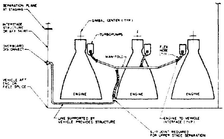 Figure 9-6.-Typical pump seal drain schematic.
Cryogenic Propellant Bleed Lines
Cryogenic propellant engine systems with turbopump feed may experience difficulties during start if the metal parts containing cryogenic fluid are at ambient or insufficiently low temperatures, and if the fluids in the volumes below the tank outlet are superheated and form gas pockets. Since the pressure upon opening of the main valves and start of the turbopumps will further reduce the static pressure at the pump inlet, accelerated gas production will result. This, in turn, may lead to pump cavitation and starving of the gas generator. To prevent this, a continuous bleed from a point farthest downstream from the pump inlet is applied until shortly before engine start. In this manner, fresh liquid at tank bulk temperature will continuously replace the warming fluid, and cool the containing metal parts. To avoid hazardous conditions at the launch site, the bleeds, particularly if they can form combustible or explosive mixtures, are ducted away. To make this possible, a line connection from the engine to the vehicle and beyond is required. The lines are generally made of wire-braided flexible hoses and tubings.
A special case is presented by cryogenic engines in upper stages which will not start until some time after the bleeds have been closed at liftoff, or which have to start after prolonged cruising periods. Here, a recirculation system which returns the fluids to the tanks rather than dumping them overboard is preferred. Lines across the interface between engine and vehicle are required. Bleed and recirculation flows can be minimized if the vehicle builder provides means, such as subcooling, insulation, avoidance of temperature stratification, maximum economic tank pressure to keep the temperature of the bulk sufficiently below the boiling temperature at operating tank pressures. In some cases, prechilling of metal parts exposed to cryogenic fluids may be advantageously accomplished by cooling media supplied from ground through a vehicle disconnect to the engine. Routing of all lines mentioned will be similar to drain lines (fig. 9-6).
Purge Lines
During the start and shutdown sequences, and for prerun and postrun servicing, inert gas purges are frequently required to keep a system dry, to prevent combustible mixtures from forming, or to expel residual propellants. If they are continuous during ground hold, it is advantageous to feed them from ground to avoid increased flight weight. This requires connecting lines from the engine to the vehicle. It is strongly recommended that entirely separate purge systems for each propellant be employed to avoid backup of one fluid into the system of the other. Check valves are not considered as reliable as strict separation. For engine design we are concerned here only with those purges which connect directly to an inlet port of an engine part, such as the thrust chamber cooling jacket or injector manifold. From the viewpoint of the environment in which the engine must operate, the engine designer should additionally specify the purges to be provided by the vehicle builder to condition the engine compartment as needed. All purge lines can be made of wire-braided flexible hoses and tubings and may be routed as are the drain lines.
Hydraulic Lines
Various high-pressure hydraulic lines are used in a liquid rocket engine for hydraulic actuating, lubrication, etc. All lines must permit flexure and must be of the proper size and pressure rating. Most of the hydraulic lines are made of wire-braided flexible hoses and tubings.
Turbine-Drive, High-Pressure, Hot-Gas Ducts
In most turbopump-feed engines, the gas generator is connected directly to the turbine inlet; thus, there is no need for ducting. In some designs, however, high-pressure hot-gas ducts are required to connect between gas generator and turbines (in systems with two individual turbopumps), or between main thrust chamber bleedoff ports and turbines (tapoff gas-turbine-drive systems). These ducts usually consist of rigid and flexible sections made of stainless steels and nickel-based alloys, for service temperatures up to approximately . The ducts must be capable of absorbing considerable deflections from thermal expansion, in addition to deflections due to misalinements and dynamic loads.
Turbine-Exhaust, Hot-Gas Ducts
The hot gases from the turbine exhaust may be ducted to near the main chamber nozzle exit or into a thrust chamber exhaust manifold. Most turbine-exhaust ducts are of welded stainless steel or nickel-alloy, sheet-metal construction. Bellows sections permit the degree of movement required by the system for thermal expansion, misalinements, and tolerances. In most cryogenic propellant systems, a heat exchanger is incorporated in the exhaust duct assembly to vaporize one of the propellants, usually LOX, for tank pressurization (fig. 5-7).
Thrust Mounts
The thrust mount transmits the thrust loads between engine and vehicle thrust frame. In some designs (fig. 2-4), the thrust mount also serves as the structural mount for many other major components of the engine system. Thrust mounts usually consist of truss members of tubular and box shape, made of aluminum alloy or alloy steels. In engine systems using fixed thrust mounts, thrust vector control is accomplished by swiveling the thrust chamber, or by other means such as jet vanes, secondary injection, or jetavators.
Gimbal Mount Assemblies
In most large turbopump-fed engine systems (figs. 3-2, 3-4, and 9-1), the complete engine assembly is gimbaled at a universal-joint-type gimbal mount assembly which connects the thrust chamber to the vehicle thrust structure.
Turbopump and Other Component Mounts
Turbopump mounts (fig. 9-1) are used to secure turbopumps to thrust chamber or other structural members, such as the thrust mount. They often consist of welded tubular trusses, forged structural members, and flexible end joints. In some designs, rigid-type, pump-discharge propellant ducts are used as members of the turbopump mounts. Most propellant valves are fastened directly to the thrust chamber or gas generator. Other control components and small storage vessels may be secured by aluminum-alloy sheetmetal brackets.